1jz vvti ecu pinout / sc300 body pinout
 02-11-11, 05:48 AM
#16
Pole Position
Thread Starter
iTrader: (1)

Join Date: Oct 2007
Location: michigan
Posts: 236
Likes: 0
Received 0 Likes
on
0 Posts
thank you!
I do not have my stock harness anymore. i either have to buy one used to get the connectors for the sc300 body, or buy the connectors at toyota and pin them.
here is all the work i have done looking at sc300 wiring diagrams, i am not going to use any of the ABS, TRAC, diagnosis or check connectors and A/T stuff. but here is the body conectors info from the sc300 spent hours looking at wiring diagrams and write everything down. i had a nice excel sheet but it is what it looks like after a copy and paste.
Connector - description 2jz wiring diagram - 1jz vvti relation
IJ1-1 FP, From Check connector for fuel pump ECU check connector only
IJ1-2 vsv for water valve A/C power to A/C ECU
IJ1-3 IG2 (B+), from Ignition switch TO injector 2, 4, 5, 6 power to injectors
IJ1-4 Theft detterent horn + pin 2 power to theft horn
IJ1-5
IJ1-6 NEUTRAL START SW (A/T) automatic only
IJ1-7 B+ To Igniter and ignition coil, 1, 3 power to igniter and injectors
IJ1-8 DI, fuel pump ECU control fuel pump ecu control
IJ1-9 Theft detterent horn - pin 1 gnd for theft horn
IJ1-10 A/T indicator sw, or M/T power for speed sensor#1 pin1
IJ1-11
IJ1-12 B+ From EB2 pin1 ECU connector J pin13 (check if spliced with starter connector c pin1 and connect to EB2 pin 1)
IJ1-13 TRAC ECU GND
IJ1-14 FPC, Fuel pump ECU power. OR gnd from power for coil Relay ECU connector H pin4, gnd for Power for fuel pump coil relay
IJ2-1
IJ2-2 ETC, cruise control ECU, OD1 on ECU
IJ2-3 SP1, To ECU from speed sensor From cluster ECU connector G pin 12 apparently used to enable VSS, see if still gonna show speed on cluster
IJ2-4 IDL, cruise control ECU
IJ2-5 L (B+ To Alternator connector B pin2) connect to alternator L
IJ2-6 SOL+ to PPS Solenoid pin 1 connect to PPS solenoid pin1
IJ2-7 STP, From stop light SW TO STP on ECU, also trac ecu STP ECU connector G pin 25
IJ2-8 From clutch start SW TO EB1 pin3 connect from IJ2-8 to EB1 pin 3
IJ2-9 OD, cruise control ECU
IJ2-10
IJ2-11 IGSW, To ECU, From Ignition switch after IGN fuse ECU connector G pin9
IJ2-12 TRAC IG1
IJ2-13 IG (To Alternator connector B pin3) connect alternator connector B pin 3 in IJ2 pin13
IJ2-14
IJ2-15
IJ2-16 SOL- to PPS solenoid pin 2 connect to PPs solenoid pin2
IJ2-17
IK1-1
IK1-2 TE2, From ECU to TDCL ECU connector G pin11 for diagnosis connector
IK1-3 VF1, From ECU to Total Diagnose Communication Link (TDCL) ?? For diagnosis connector
IK1-4 TE1, From ECU to TDCL ECU connector H pin5 for diagnosis connector
IK1-5 TT, From ECU to TDCL (A/T only)
IK1-6 from speed sensor#1 pin 2 to cluster connect speed sensor to IK1-6
IK1-7 from speed sensor#1 pin 3 to cluster connect speed sensor to IK1-7
IK1-8 TAC, from TAC on igniter to speedo on cluster Also spliced to IG- on check connector connect TAC from Igniter to IK1-8
IK1-9 From Water Temp sender to cluster Connect water temp sender to IK1-9 to ECU connector I pin20 (THW)
IK1-10 ABS
IK1-11
IK1-12
IK1-13
IK1-14
IK1-15
IK1-16
IK1-17
IK1-18
IK1-19
IK1-20 from oil pressure SW to cluster light connect oil pressure switch to IK1-20
IK1-21 P, To ECU, ETC pattern select SW (A/T only)
IK1-22 OD2, To ecu From automatic indicator light (A/T only)
IK1-23
IK2-1
IK2-2 TRAC, ABS
IK2-3 TRAC TDCL
IK2-4 TRAC
IK2-5 TRAC
IK2-6
IK2-7
IK2-8
IK2-9 W, From ECU to Check engine light cluster, also TDCL and TR5 trac ecu ECU Connector H pin3 ??
IK2-10 From Engine oil level warning sw to cluster light Connect engine oil level sw to IK2-10
IK2-11
IK2-12 OX3, From ECU to O2 SUB (california car only)
IK2-13 TRAC parking brake sw
IK2-14
IK2-15 TRAC BAT
IK2-16 TRAC CSW
IK2-17
IK2-18 TRAC ABSO
IK2-19
IK2-20
IK2-21
IK2-22 HT, From ECU (california car only) O2 SUB
IK2-23
IK2-24 From Ground rear side of cylinder head connect ground from rear of cylinder head to IK2-24
IK2-25 ABS
EB1-1 To coil of magnetic clutch connect magnetic clutch to EB1-1
EB1-2 ACMG, To ECU From Magnetic clutch relay ECU connector G pin5 to EB1-2
EB1-3 Clutch start SW (M/T) connect IJ2 pin8, Neutral start switch (A/T) Connect to IJ2 pin8
EB1-4 BATT, to ECU ECU connector G pin14
EB1-5
EB1-6 ABS
EB1-7
EB1-8 M-REL, to ECU ECU connector H pin2
EB2-1 STA, From starter connector C pin1 also spliced to ECU, to B+ check connector, To IJ1 pin 12 ECU connector J pin13 (check if spliced with starter connector c pin1 and connect to EB2 pin 1)
EB2-2 S (To alternator connector B pin1) Connect connector B pin1 from alternator to EB2-2
EB2-3 B+, to B+ on ECU ECU connector G pin 22-23
1jz ECU connectors (28pin "G", 16pin "H", 22pin "I", 34pin "J")
Last edited by adam8103; 02-11-11 at 05:52 AM.

 02-11-11, 01:13 PM
#20
Pole Position
Thread Starter
iTrader: (1)
Join Date: Oct 2007
Location: michigan
Posts: 236
Likes: 0
Received 0 Likes
on
0 Posts
Exactly what SOL is for! in your file you are saying ground to injectors, i am just making sure you know it is actually power that you have to bring to them as well as your coils and such. i have to double check for the alt wire on IJ1-5 i wrote it there and you wrote it on IJ2-5. i will make sure on my wiring diagram which one is right. You made this pinout for which purpous?
i did not know it was possible to attach a file but now i do here it is then
I put in red what was in ACCOUNT2X pinout and not in mine and i will doublecheck
i did not know it was possible to attach a file but now i do here it is then
I put in red what was in ACCOUNT2X pinout and not in mine and i will doublecheck
Last edited by adam8103; 02-11-11 at 01:19 PM.
02-11-11, 04:01 PM
#21
SOL goes to the power steering rack, it controls the SOLenoid there.
When I was depining 1J1 I found two pins (3 & 7) that had a LOT of wires attached to them. Using common sense I deduced they were grounds and just labeled them based on what they seemed to ground. Maybe they are the opposite and actually power.
Someone else posted this on the forums and I used it for reference making my pinout. That's how I was able to label the pins SOL without even knowing what they were.
Last edited by account2x; 02-11-11 at 04:18 PM.
02-12-11, 08:59 AM
#24
Pole Position
Thread Starter
iTrader: (1)
Join Date: Oct 2007
Location: michigan
Posts: 236
Likes: 0
Received 0 Likes
on
0 Posts
I double checked for the alternator wire i put on IJ2-5, it goes on IJ2-5 so change yours for IJ2-5
not able to upload this file but it is in the wiring diagram.
not able to upload this file but it is in the wiring diagram.
Last edited by adam8103; 02-12-11 at 09:13 AM.
02-12-11, 09:33 AM
#25
How did you double check?
I just doubled checked myself. IJ1 can accept two different sizes of terminals. To simply matters I will name the larger one large and the smaller one medium. IJ2 can only accept 1 size thenceforth called small.
The black wire from the alternator housing has a small size terminal and thus fits into IJ2.
The yellow wire from the alternator housing has a medium sized terminal and thus CANNOT fit into IJ2. It can however fit into IJ1.
02-12-11, 08:49 PM
#26
Pole Position
Thread Starter
iTrader: (1)
Join Date: Oct 2007
Location: michigan
Posts: 236
Likes: 0
Received 0 Likes
on
0 Posts
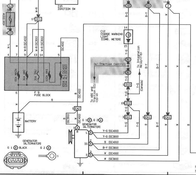
i checked it on the lexus wiring diagram from the lexus manual. i attached the charging wiring diagram. you can see IJ2-5 i do not have my stoch 2js harness anymore so i go with the lexus manual, i dont mind if i am wrong i just want everything to be at the right place.. and from the manual it looks like it is supposed to be IJ2-5 but it might be a mistake in the wiring diagram.
Last edited by adam8103; 02-12-11 at 08:52 PM.
 02-13-11, 06:00 PM
#29
Pole Position
Thread Starter
iTrader: (1)
Join Date: Oct 2007
Location: michigan
Posts: 236
Likes: 0
Received 0 Likes
on
0 Posts
the manual i have has a mistake on one page i do have the IJ2-5 and on another one it shows IJ1-5, i will go with account2x since he has the connector and pin that does not fit in IJ2-5.
so IJ1-5 it is.
so IJ1-5 it is.
03-03-11, 05:25 PM
#30
Pole Position
Thread Starter
iTrader: (1)
Join Date: Oct 2007
Location: michigan
Posts: 236
Likes: 0
Received 0 Likes
on
0 Posts
i just received my 2jz harness to take the body connectors out of it, i updated my list i followed each wires to make sure, it was an automatic harness tho that the guy converted to a 5 speed. i also found two other connectors close by the IJ1, IJ2... etc and i named them D1 and D2 as i dont know their real name.
Last edited by adam8103; 03-04-11 at 11:44 AM.